Cats2D Multiphysics > Research Topics > Rotating baffle vertical Bridgman method
Novel means to modify growth interface
shape in vertical Bridgman crystal growth
Unpublished results Copyright © 2017 Andrew Yeckel, all rights reserved
This draft posted on August 3rd, 2017
Comment
This work was carried out without any access to scientific
literature behind paywalls. Recently I gained temporary access
and discovered that the method described here, the use of a
submerged insulator, has been previously identified by
Alexander Ostrogorsky in his extensive work on submerged
heater systems, which he innovated over 30 years ago. I was
already aware of his submerged heater-based work and have
cited some of it in my published articles on this topic, but I
was unaware that he has also studied the same passive approach
that I claimed is novel in the title of this article. Hence
I've struck out the word novel. Note, however, the work I
report here supplements rather than duplicates his earlier
research.
Eventually I intend to put together a bibliography for this
article. In the meantime, see A.G. Ostrogorsky, Disk-driven
flows and interface shape in vertical Bridgman growth with a
baffle, Progress in Crystal Growth and Characterization of
Materials, 67 (2021) 100512, and papers by Mayer and
Ostrogorsky referenced therein, for a review of his work in
this area.
Preface
This is the first in a series of articles I intend to write on various aspects of convective heat and mass transfer in crystal growth systems. My goal is to present an accumulation of knowledge that is both comprehensive and easily digestible, rather than simply making an addition to knowledge in the form of a traditional journal article. Undoubtedly I will add new angles to the story as time goes on, building on earlier material. Towards this end I've put together a graphics-rich presentation that emphasizes material of a tutorial nature to better motivate its research findings. Details inessential to understanding those findings, such as the modeling equations, bibliographic references, and other background are provided in depth but hidden behind links. The format will evolve over time, but, as always, I promise you all the rigor and accuracy that Cats2D and I can deliver.
1. Introduction
I show here a conventional vertical Bridgman system side by side with a novel configuration based on a low conductivity baffle inserted into the melt close to the growth interface. The baffle may also be rotated. The material properties of the melt and crystal are those of cadmium telluride. The baffle modifies local heat transfer in such a way to invert the interface shape from concave to convex under it, bringing the system closer to the ideal scenario of an interface that is mildly convex everywhere. However, a locally concave region persists near the ampoule wall. In this article I explore how these modifications work, and test an idea on how to eliminate that pesky concave region at the wall.

Obviously this system looks similar to the submerged heater system studied by Ostrogorsky, and the AHP system of Gonik and Golyshev, both introduced around 1990. However, neither system has taken hold as a significant industrial process. I think two factors have played a role in stalling the refinement and acceptance of these methods. First, their effectiveness requires reasonably good control of the width of the gap between heater and growth interface, something not easily observed during growth. Transient thermal effects cause the growth rate to deviate significantly from the furnace translation rate in the early and late stages of growth, making it difficult to infer the gap size. Should the gap be too large the method will be ineffective, and too small the method may fail altogether if the heater contacts the interface.
Second, the method requires construction of a heater from refractory materials that are non-reactive with the melt. It must be supplied by power and controlled by sensors and instrumentation, which adds significant complexity to the system. The method appears to be a risky and expensive retrofit that is likely to require iterative improvements to the heater design without guarantee of success. As an active method it introduces new opportunities for failure, especially since it is close to the interface. Deviations in power to the heater and the distribution of heat generated by it will have a first order effect on the gap, which presents a narrow target for the sensors and controller to manage.
The baffle I describe here also must be constructed from suitable non-reactive refractory materials, but otherwise is quite simple. Also, it is a passive method the behavior of which is much more narrowly bounded than an active heater. The only variable requiring active control is the gap size. Modeling a solid material of uniform conductivity is also simpler and more accurate than modeling a heater constructed of heterogeneous materials with internal geometric complexity, hence it might be easier to infer the gap size aided by modeling. A single thermocouple on the axis might provide sufficient information to maintain a reasonable gap, since a solid baffle will not be subject to hot or cold spots that an active heater would be prone to exhibit.
In the results shown below, I've located the growth interface near the middle of a long ampoule. This makes for a long conduction path for latent heat of solidification to escape down the axis of the crystal. As a consequence, heat tends to be forced laterally out the side of the ampoule, which causes undesirable concave interface bending. When the ampoule is short along its axis, it is relatively easy to invert the shape of the interface by removing heat from bottom of the crystal, for example by the cold finger approach of Dieguez. The goal here is to learn how to invert the interface in long ampoules where it is much harder to do so.
2. Why is interface shape important in melt crystal growth?
Historically, yields have been low for Bridgman-grown cadmium telluride and related compounds. The Bridgman method has been preferred for growing these materials because it is a contained system, which makes it easier to control over-pressure of highly volatile cadmium than an open system such as Czochralski. Maintaining this over-pressure is essential to controlling crystal stoichiometry, which is critical to tailoring its electronic properties. The downside is that contact between the growth interface and ampoule wall causes large local thermal gradients and mechanical stresses, and also surface energy interactions between the dissimilar materials, all with unknown effect. Cadmium telluride compounds are highly prone to formation of extended defects during growth, which has been attributed to these phenomena, often vaguely described as wall interactions.
Evidence that wall interactions do spawn extended defects has been observed in studies of detached crystal growth conducted in low earth orbit. Etch pit density at the outer surface of the crystal was dramatically reduced during periods of detached growth of cadmium zinc telluride in these experiments. Detached growth might be a viable alternative to grow high quality cadmium telluride compounds, and it greatly interests me, but in this work we must live with these wall interactions, so we must find a strategy to minimize the impact of defect formation on the crystal.
A popular conceptualization has it that defects initiated at the wall tend to grow in a direction approximately perpendicular to the growth interface, and therefore maintaining a convex interface shape will avoid propagation of the defects towards the center of the crystal. The argument is essentially geometric in nature, and there is some experimental evidence to support it, but, lacking any sort of model to describe defect formation, we really don't know. Mechanical stress is caused by thermal gradients, and in particular by curvature of the temperature field, so anything we do to reduce interface curvature also reduces thermal stress at the wall, which might also reduce defect formation. Surface interactions (essentially wettability), are probably important and will depend on ampoule material and any surface coating if present.
The confused picture I've presented here makes it difficult to precisely state a goal or metric for optimization. Since reducing interface curvature, whether convex or concave, is good for reducing stress, we might view any reduction of interface deflection to be a step in the right direction. On the other hand, defect formation might not be affected much by stress and we must rely instead on strictly maintaining a convex interface to isolate the defects. The view I am adopting here is that a convex interface shape would almost certainly be helpful, but that it might sometimes be useful to make a concave interface less so, particularly to avoid very deep interfaces. Lurking unavoidably in the background is the unknown role of surface wettability or other chemical interaction between ampoule and melt that might negatively impact any strategy suggested here.
3. Model equations and conditions of simulation
Governing equations of the model were auto-generated by Cats2D. Unfortunately I haven't included boundary conditions yet in the LaTeX equation generator. Rest assured that I will. This model has been discussed many places, starting with Kuppurao et al. (1995). Its implementation in Cats2D is demonstrated in several works of mine (1999, 2000, 2001, 2005). This is a variation on the Stefan problem. I've put together a slide show (1.5 Mb PDF) for newcomers that explains how interfacial boundary conditions are formulated for this problem. Of course the methods used by Cats2D to solve this problem are described in great length in the user manual.
Tables of physical and operating parameters for the base case were also auto-generated by Cats2D. The first four tables are dimensional problem inputs. The final three tables give definitions and values for dimensionless parameters computed from the input parameters. The properties are those of cadmium telluride in a quartz ampoule of 5 cm diameter. The system is heated by radiation from an effective furnace temperature profile with a nominal gradient of 500 K/m. The rate of heat transfer to the ampoule is fast enough to impose a linear axial temperature distribution on the outer surface of the ampoule with gradient ~490 K/m.
Here is a tarball with input files and converged solutions for any of my friends who want to play around with this problem. To read the base case solution, test its convergence, and create LaTeX files with governing equations and parameter tables, enter
flow -dquartz -n1 -r -t -p -b
on the shell command line. Note the simplicity of the control file for this problem. Cats2D is easy.
4. Tutorial on standard vertical Bridgman growth
Before studying the effect of the insulating baffle it is worthwhile examining why interface bending occurs in the first place. Primary causes are unequal thermal conductivities in melt and solid, and latent heat of solidification. Convective heat transfer in the melt and ampoule conductivity are also important, but their effects on interface shape are secondary. In the following sections I walk you through the basics of Bridgman growth by explaining how each of these factors influence interface shape, both individually and collectively.
Something I overlook entirely here is composition-dependent melting temperature, which complicates matters considerably. Gaining a strong foothold in the simpler case of a constant melting temperature will move us a long ways towards understanding that situation, however.
Study 1 — Heat transfer by conduction only
Effect of unequal thermal conductivities
Growth rate is zero in these calculations, which are cases 1
to 3 in the conduction solution directory. The
interface is flat when thermal conductivities are equal (left
plot). For semiconductor crystals the conductivity is
generally higher in the melt than the solid, which promotes
concave bending of the interface (middle plot). For ionic
crystals the converse is true and convex bending is promoted
(right plot).

Since the conduction problem is linear, the size of the system has no effect on interface shape. The interface deflection scaled by system radius, in percent, remains constant, as does the angle of intersection between the interface and the ampoule wall.
Heat flux paths, plotted below for cases 2 and 3, show how heat flows outward when the melt is more conductive than the crystal, and inward when the converse is true. The interface bends because axial heat transfer is slower in one domain than in the other, owing to different thermal conductivities. The mismatch causes a radial thermal gradient to form that drives heat laterally at the interface. The larger the ratio of radial gradient to axial gradient, the greater the interface bending.

Bending of the isotherms can be avoided by eliminating radial gradients, but this leaves only one pathway for the heat to get out, which is through the crystal. If conductivity is lower in the crystal than the melt it is necessary to enhance heat transfer in the lower part of the ampoule somehow. The most obvious way to do this is to increase the thermal gradient in the crystal, which is discussed below.
Effect of latent heat of solidification
The same calculations are repeated with growth rate of 1
mm/hr, which are cases 4 to 6 in the conduction solution
directory. Latent heat always tends to bend the interface into
a concave shape, even when thermal conductivities are equal
(left plot). This effect exacerbates the problem of concave
interface bending caused by higher conductivity in the melt
(middle plot). We would prefer lower conductivity in the melt,
which reduces concave bending (right plot). But our system
chooses us, not the other way around, so if we are studying
cadmium telluride we need to operate in the unfortunate realm
of that middle plot with its deeply concave shape.

When conductivity is higher in the melt than the crystal (case 5, below left), the flow of heat through the melt slows down considerably near the interface where it is opposed by the release of latent heat. This deceleration magnifies the deflection of the paths. In the converse situation (case 6, below right), the flow of heat accelerates in the crystal where conductivity is higher than the melt. This acceleration is nearly enough to carry the latent heat through the crystal, which causes the paths to straighten out.

The thermophysical values studied here are generic, but the situation on the left is reasonably representative of cadmium telluride in a quartz ampoule. In no case does the interface achieve the ideal of a convex shape, though it has come close in the plot on the right, where the advantage of a lower thermal conductivity in the melt has nearly offset the latent heat effect.
Effect of furnace temperature distribution
The degree of bending is strongly affected by the axial temperature distribution in the furnace. I've considered three different temperature profiles, shown below. A linear profile of constant gradient is used unless specified otherwise. Other profiles studied are the roll-off type of profile used in Yeckel et al. (1999), and the three-zone type used in Kuppurao et al. (1995) in which hot and cold zones are separated by an insulated zone.
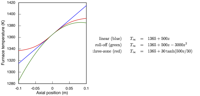
All three profiles intersect at the same point in the ampoule, with gradient of 500 K/m at the melting temperature of 1365 K. The roll-off and three-zone profiles are similar in the upper part of the ampoule, with gradient that gradually decreases towards the top of it. In the lower part of the ampoule they are quite different. In the roll-off profile the gradient increases towards the bottom of the ampoule, whereas it decreases in the three-zone profile.
When using a computer model it is tempting to carry things too far. We might, for example, impose much more extreme changes in the temperature distribution, and in the rates of heat transfer, than could be established in a real furnace. The profiles I've chosen here pretty well cover the range of generic possibilities in a real furnace, and I've deliberately avoided impractically large gradients or heat transfer rates.
To see how this affects interface bending, I've recomputed
the worst case from above using each of these profiles, which
are cases 1 to 3 in the tprofile solution
directory. On the left is the linear profile (same as conduction
case 5 above). In the middle is the roll-off profile, which
reduces the temperature in both the melt and crystal compared
to the linear profile. The larger gradient in the lower part
of the ampoule enhances axial heat transfer in the crystal,
which reduces interface bending by one-third. On the right is
the three-zone profile, which also reduces the temperature in
the melt, but raises it in the crystal. The gradient in the
lower part of the ampoule is reduced and axial heat transfer
in the crystal is diminished, causing a slight increase in
curvature of the interface compared to the linear profile.

Clearly the roll-off strategy performs better than the three-zone strategy for reducing concave bending of the interface in these results, but this conclusion is based on matching the gradient at the interface. Any of these profiles can be changed to increase the gradient at the interface, which will always tend to reduce bending. But doubling the gradient in the linear and roll-off profiles also doubles the total difference in temperature between bottom and top of the ampoule, which might be undesirable or infeasible. In contrast, the three-zone profile is designed to allow a larger gradient without greatly increasing the total temperature difference. Perhaps a fairer comparison is to consider a larger gradient for the three-zone profile than the other profiles, so I've re-computed the three-zone result after doubling the gradient to 1000 K/m, which is the red curve shown below.
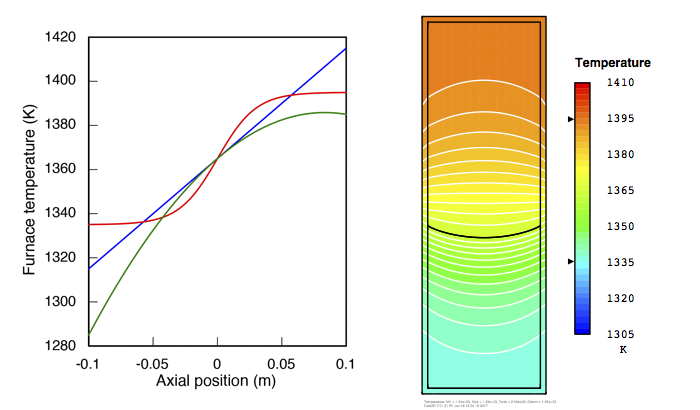
Doubling the gradient only reduces interface bending (the ratio of interface deflection to crystal radius) from 26% to 22%. For comparison, the linear and roll-off profiles at the lower gradient have bending of 24%, and 16%, respectively, reinforcing the conclusion that the roll-off strategy is superior if our goal is to reduce concave interface bending. Either way, though, we're never going to completely flatten the interface just by manipulating the furnace profile.
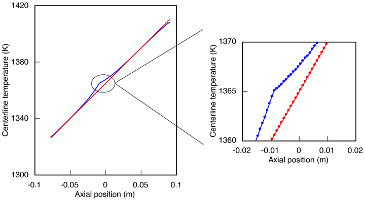
In the plots below, I show how the temperature varies along the center axis of the ampoule (the blue curve) compared to the furnace profile (the red curve), for both the linear and roll-off profiles. In the upper and lower regions of the ampoule, the center axis temperature follows the furnace temperature closely except near the interface, where it is elevated by several degrees K. The maximum difference between the blue curve and red curve occurs at the interface. It is about 5 K for the linear profile, shown first:
The difference is smaller, about 3 K, for the roll-off profile shown next:
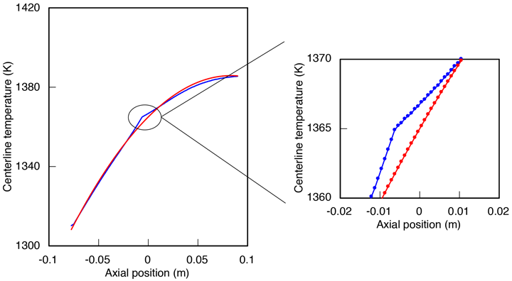
This elevation of the temperature simultaneously increases the axial gradient in the crystal and lowers it in the melt. As a consequence, heat is conducted away through the crystal more quickly and arrives from the melt more slowly. These effects are needed to mitigate latent heat generated at the interface, but on their own are insufficient to satisfy the interfacial energy balance. Elevating the temperature at the center axis also sets up a radial temperature gradient that removes heat in the lateral direction. To eliminate interface bending we need to eliminate this radial gradient. This presents a conundrum, because it asks us match the blue curve, which must have a discontinuity in its gradient, to the red curve, which must have continuous gradients everywhere.
Effect of ampoule material
Cadmium telluride-related compounds have been grown in graphite, quartz, and PBN (pyrolytic boron nitride) ampoules. Thermal conductivity in graphite can be mildly anisotropic, but is so high in any case that anisotropy is unlikely to be important. PBN is strongly anisotropic, similar to graphite in the axial direction (60 W/m-s) and similar to quartz through the wall thickness (2 W/m-s). Quartz conductivity is isotropic but it can transmit radiation, and quartz ampoules are sometimes coated inside with a thin layer of boron nitride, complicating matters further. In any case we can expect some anisotropic behavior with heat transfer enhanced in the lateral direction by radiation to an unknown degree.
I consider quartz and graphite, treating both as isotropic,
which represent the practical upper and lower bounds on
conductivity. These are cases 1 and 2 in the ampoule
solution directory. I also perform anisotropic calculations in
which I treat enhanced axial heat transfer in a PBN crucible,
which is case 3. First let's see what we can learn from the
simpler isotropic cases, computed for a linear furnace profile
with 500 K/m gradient. On the left I show isotherms and heat
flux paths for the quartz ampoule (2.5 W/m-s) and on the right
for the graphite ampoule (85 W/m-s).

The most obvious difference is that most of the heat flow is diverted into the highly conductive graphite ampoule. Interface bending is greater in graphite, 33% compared to 26% in quartz. There is also a modest decrease in thermal gradient by 10% in the graphite ampoule, which can be seen by comparing the isotherm spacing in the two plots (and also by comparing the carets on the temperature legends). I've experimented with increasing the furnace gradient to compensate for this tendency in graphite, but reducing bending from 33% to 26% requires nearly doubling the furnace gradient to 959 K/m. Applying this same furnace gradient to the quartz ampoule reduces bending from 26% to 21%, so quartz is always at an advantage to graphite.
The PBN ampoule (not shown here) gives results quite similar to graphite, with interface bending slightly less at 31%. Although PBN has low thermal conductivity through the ampoule wall more similar to quartz than graphite, heat conduction in this direction is relatively unimportant because the wall is thin. In contrast, heat conduction in a direction along the wall is quite important, and in this direction PBN and graphite have similar conductivities, hence the similar behavior.
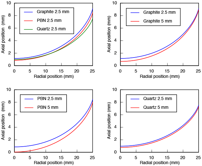
These results are summarized in the plots below, which show growth interface shape with the vertical dimension exaggerated by a factor of two. The upper left plot shows shapes in ampoules with a wall thickness of 2.5 mm. The graphite and PBN interfaces have nearly the same shape, but the PBN interface is lower in the ampoule due to its low conductivity in the lateral direction. The quartz interface is lower in the ampoule for the same reason, but obviously exhibits less bending, due to its low axial conductivity. It should be noted that graphite and PBN ampoules are both made thicker in practice than quartz ampoules, due to mechanical weakness of these materials, so I've shown plots to compare interface shape in 2.5 mm and 5 mm ampoules of each of these materials. Interface bending is worse in the thicker ampoules due to a decrease in lateral heat conduction. The effect is large in graphite and PBN ampoules, because the thicker ampoule provides a larger cross-section for channeling heat. In the quartz ampoule there is hardly any effect because this channeling effect is largely absent.
Another important consideration is the thermal gradient on the melt side of the growth interface. The gradient at the interface is generally lower than the furnace gradient, primarily because of the latent heat released by solidification. Should the gradient fall too low, which may happen at higher growth rates, the growth interface will become morphologically unstable. Below on the left I show the gradient plotted along the entire interface for the 5 mm ampoules of each material, and on the right I show a magnified region near the wall (symbols indicate node locations to give a sense of the discretization.) The thermal gradient at the center axis, where it is lowest, is 221 K/m in the graphite ampoule, 223 K/m in the PBN ampoule, and 259 K/m in the quartz ampoule, all of which are much lower than the furnace gradient of 500 K/m. Quartz gains another advantage here for its tendency to support a thermal gradient better than the other materials.
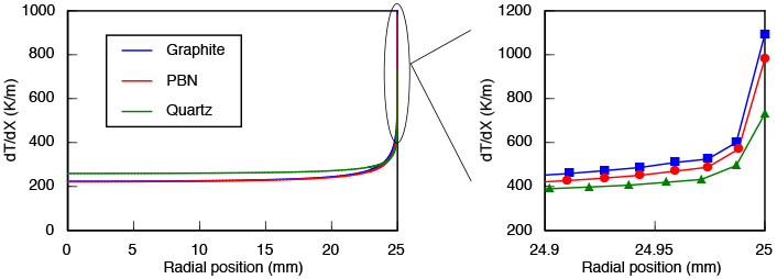
Near the wall there is a sharp increase in thermal gradient. The magnified region indicates that the gradient has a finite value at the wall, but in fact the equations are singular at the triple junction between melt, crystal, and ampoule due to differing thermal conductivities, and also due to production of latent heat. So this finite wall value is simply wrong, an artifact of the discretization. I have used Richardson extrapolation to confirm that the wall value increases without bound as the mesh is refined.. This singularity is integrable, however, so the governing equations are regular and well behaved. The important thing to note here is that the thermal gradients do grow large when the interface bending is large, which is certain to concentrate thermal stress near this triple line, and this effect is worse in the highly conducting ampoules than it is in quartz. Eventually I will return to these results to perform some calculations of von Mises stress to explore this issue more quantitatively.
Discussion of heat transfer by conduction only
The results I've presented above are obvious, for the most part. To avoid interface bending, the gradient must be larger in the crystal than the melt, enough larger to both compensate for the difference in thermal conductivities and to carry away the latent heat of solidification. Otherwise heat must be forced out laterally. This strategy has already appeared in a few forms, for example the "cold-finger" furnace design employed by Ernesto Dieguez's group to create a large gradient at the bottom of the ampoule. Also, Zhang et al. (2012) have published these Cats2D results showing that a "bell-curve" profile can accomplish the same thing by imposing a sharp change in gradient at the growth interface.
There are problems with both these approaches, however. The cold finger design is effective within a limited range of the ampoule bottom and therefore is unsuitable for long ampoules. The bell-curve approach relies on a fictitious furnace temperature distribution that exhibits a large discontinuity, making it infeasible in practice. Neither approach gets the job done on its own, yet both have something to offer when paired with the insulating baffle modification introduced below.
These results come with the caveat that convective heat transport, neglected here, is quite important in vertical Bridgman growth. Natural convection is always present, Marangoni convection can occur in non-confined melts, and forced convection may be induced by rotating or vibrating the ampoule. Quantitative work demands we include these phenomena when present. But in terms of growth interface shape, these effects can only mitigate bending to some degree. They cannot reverse it on their own, and sometimes they make it worse. We see how in the next section.
Study 2 — Heat transfer by conduction and convection
Effect of furnace temperature distribution
Temperature isotherms and streamlines are shown below for
natural convection in a quartz ampoule of 5 cm inner diameter
(cases 1 and 4 in quartz solution directory).
Results on the left were computed using the linear furnace
profile, and on the right using the roll-off furnace profile.
I've assumed that the melt is fully enclosed, though often in
practice there is a space above the melt. In a long ampoule
the flow field at the top of the melt is unimportant to the
conclusions developed here anyway, so I have ignored Marangoni
flow arising at the upper surface of the melt.

The upper vortex circulates counter-clockwise, rising up the wall and sinking in the center. The upper vortex is much stronger for the roll-off profile, which has a destabilizing gradient near the top, than the linear profile, which is strongly stabilizing throughout the melt. The lower vortex, which circulates clockwise, is much more important, however, since it helps to carry away latent heat generated at the interface. This results in a smaller thermal gradient at the melt side and lessens the heat that must be carried away through the crystal:
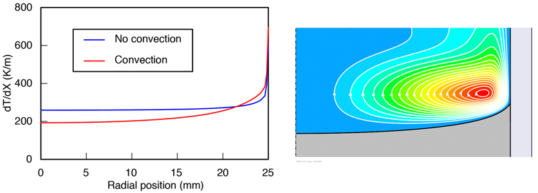
Lateral heat transfer is also promoted by convection, which has the effect of reducing the thermal gradient in the radial direction. This can be seen from plots of the center axis temperature vs. furnace temperature for the linear and roll-off profiles, which are closer together than the cases without convection shown above.
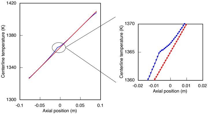
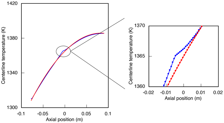
The effect of these changes is to reduce interface deflection, and also to reduce the axial thermal gradient in the melt. While this reduction in gradient might seem to bring the system closer to morphological instability, in practice it won't, because mass convection will provide a stabilizing influence.
Effect of system size
System size has a large effect on natural convection, the
intensity of which scales to the third power of the ampoule
diameter. Increasing the ampoule diameter from 5 to 7.5 cm
more than doubles the recirculation speed of the lower vortex
for the linear furnace profile (below left) and the roll-off
furnace profile (below right), which are cases 2 and 5 in the
quartz solution directory.

For the roll-off profile, a plot of the center axis temperature (the blue curve) shows that convective heat transfer has flattened the temperature gradient along the center axis in the upper melt. This sets up a large radial temperature difference (the difference between the red and blue curves) that drives natural convection near to instability. This could be a problem; time dependent flows tend to cause periodic melting back of the interface, which might cause compositional striations, and perhaps instability of the growth interface.
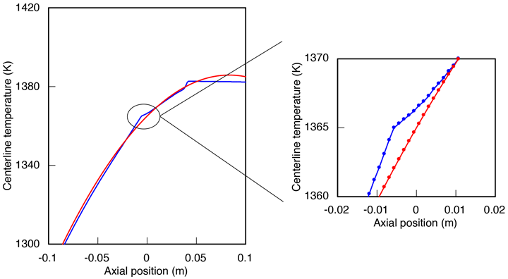
On the other hand, flow in the lower melt near the growth interface doesn't change nearly so much, and the temperature field shown in the inset above exhibits the same characteristic local elevation of temperature at the interface seen in the smaller system.
Discussion of heat transfer by conduction and convection
Natural convection is important to heat transfer and interface shape, but in a sense it is secondary to conduction in the crystal, which is always the limiting step to remove latent heat of solidification. Most importantly, natural convection in this system cannot invert a concave interface under normal conditions of growth, at most it can partially mitigate it.
Natural convection introduces a strong size effect to heat transfer in the melt, but as long as the flow remains stable, the situation doesn't change much in terms of interface shape. More heat is generated in a larger system, but the main pathways of heat transfer scale up similarly, so the impact on relative deflection of the interface is fairly mild.
I've only presented results for the quartz ampoule here, but I've computed results for the other materials and found that adding natural convection does not alter the conclusions reached earlier about graphite and PBN. Interface deflection is always lower using quartz than the more conductive materials. Whether quartz is the best ampoule material likely depends on a host of other factors, however, making this a very limited endorsement.
5. Effect of an insulating baffle on interface shape
At the start of the previous section on conventional Bridgman growth, I showed that a convex interface can exist when thermal conductivity is larger in the crystal than in the melt, which is true of ionic crystals. If so, axial conduction through the crystal can remove all of the heat conducted from the melt, and some additional heat drawn through the ampoule wall as well, causing the heat flux lines to bend inward at the growth interface. But this is untrue for CdTe and other semiconductors, in which thermal conductivity in the crystal is smaller than in the melt. This makes it impossible to conduct heat away from the interface without some lateral heat transfer outwards that causes heat flux lines to bend outward, resulting in a concave interface.
I noted earlier that our material chooses us, not the other
way around, with the implication that these thermophysical
properties are immutable. But there is a way to effectively
reduce the thermal conductivity of the melt, by displacing it
with a baffle of solid material of low conductivity submerged
near the growth interface. The effect of doing this is shown
below, on the left for a non-insulating baffle having the same
conductivity of the melt (2 W/m-K), and on the right for an
insulating baffle having conductivity ten times smaller (0.2
W/m-K). These are cases 1 and 2 in the baffle
solution directory.

In the plot on the left, the non-insulating baffle does nothing to slow down the flow of heat in the axial direction. Consequently the heat flux lines and interface shape appear much the same as they do in a conventional Bridgman system. In the plot on the right, the heat flux lines bend outward above the insulating baffle, then bend inward below it. Low conductivity of the baffle forces heat to flow around it, which reduces the rate of axial heat transfer to the interface enough that axial conduction in the crystal can remove all of it. This gives a convex interface shape except near the ampoule wall. This feels like a step in the right direction.
Next I show results for a 7.5 cm system with an insulating
baffle of 0.2 W/m-K, the same as the plot shown above right
except for the change in system size. Increasing the size of
the system causes the interface to move lower in the ampoule
and invert its shape back to concave (below left). Uniformly
reducing the furnace temperature by 1 K shifts the interface
higher in the ampoule and restores its convex shape (below
right). This demonstrates that the method scales with system
size provided we adjust the furnace environment to manage the
gap size between baffle and interface. These are cases 3 and 4
in the baffle solution directory.

The previous results were based on a fictitious insulating
material of 0.2 W/m-K, which might be unrealistically low.
However, materials that can withstand the refractory
temperatures of this system do exist with conductivity around
0.4 W/m-K. Results computed at this larger value are shown
below left for the linear furnace profile, and below right for
the roll-off furnace profile. These are cases 5 and 6 in the baffle
solution directory.

The interface has become concave for the linear profile but is partially convex for the roll-off profile at this more realistic value. As before, the roll-off profile results in a much stronger flow in the melt above the insulating baffle, but flow is suppressed in the region below it. This might be helpful in shielding the interface from time-dependent flow.
Next I show a more systematic view of the relationship between interface shape, gap size between interface and baffle, and thermal conductivity of the baffle. The gap size is varied by shifting the linear furnace temperature profile uniformly in 1 K increments. For the non-insulating baffle, reducing the gap does nothing to reduce interface deflection:
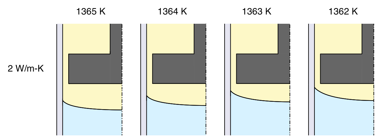
A baffle with a low but reasonable conductivity reduces interface deflection, but is unable to invert the interface for the linear furnace profile:
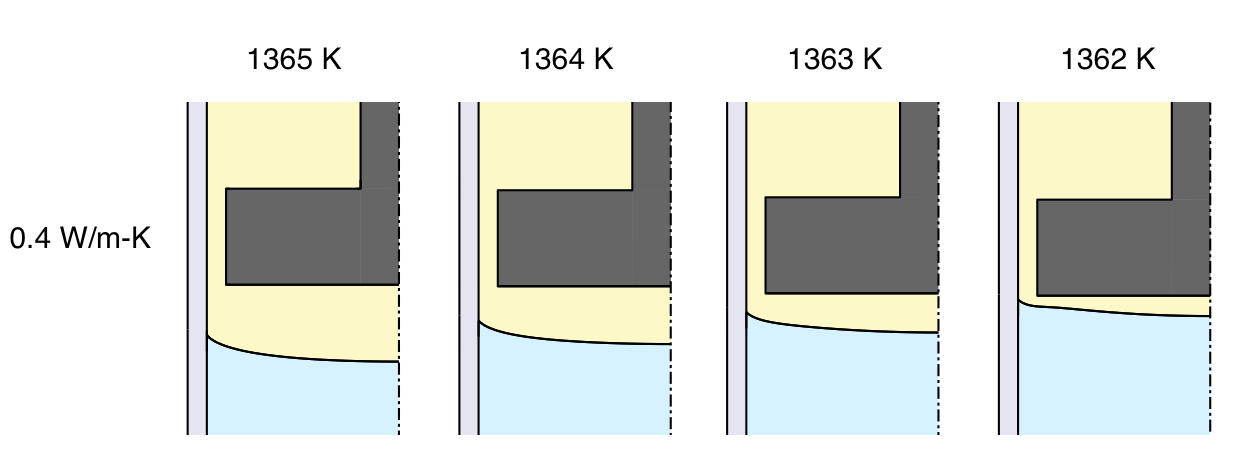
Reducing baffle conductivity to a lower value that seems plausible but might be difficult to achieve in practice, inverts the interface provided the baffle is placed close to the interface:
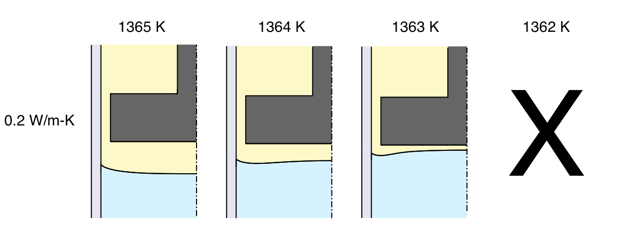
These results are promising, but not entirely satisfying. Generally we would like to use the lowest conductivity possible for the baffle, but it might be difficult to find a material insulating enough to reliably invert the central area of the interface at a reasonable gap size. Also there is the problem of concave interface deflection that persists near the ampoule wall. The first of these problems is addressed in the next section, by introducing forced convection to help carry away latent heat of solidification.
6. Rotating the baffle to convect away latent heat
Earlier I showed that adding natural convection to the problem tends to reduce interface deflection by enhancing removal of latent heat generated at the interface. But natural convection near the interface is driven by a radial thermal gradient that diminishes as the interface becomes flatter, so the effect is self-limiting and can never completely suppress interface bending. It does suggest, however, that forced convection might be used to accomplish the same thing. We can pump flow upward underneath the baffle by rotating it. The ideal flow for this purpose should be oriented upward everywhere, but this isn't possible in a closed geometry. The flow turns downward near the ampoule wall because it must turn around to form a closed recirculation. However, most of the area under the baffle experiences forced convection upward, causing the desired effect.
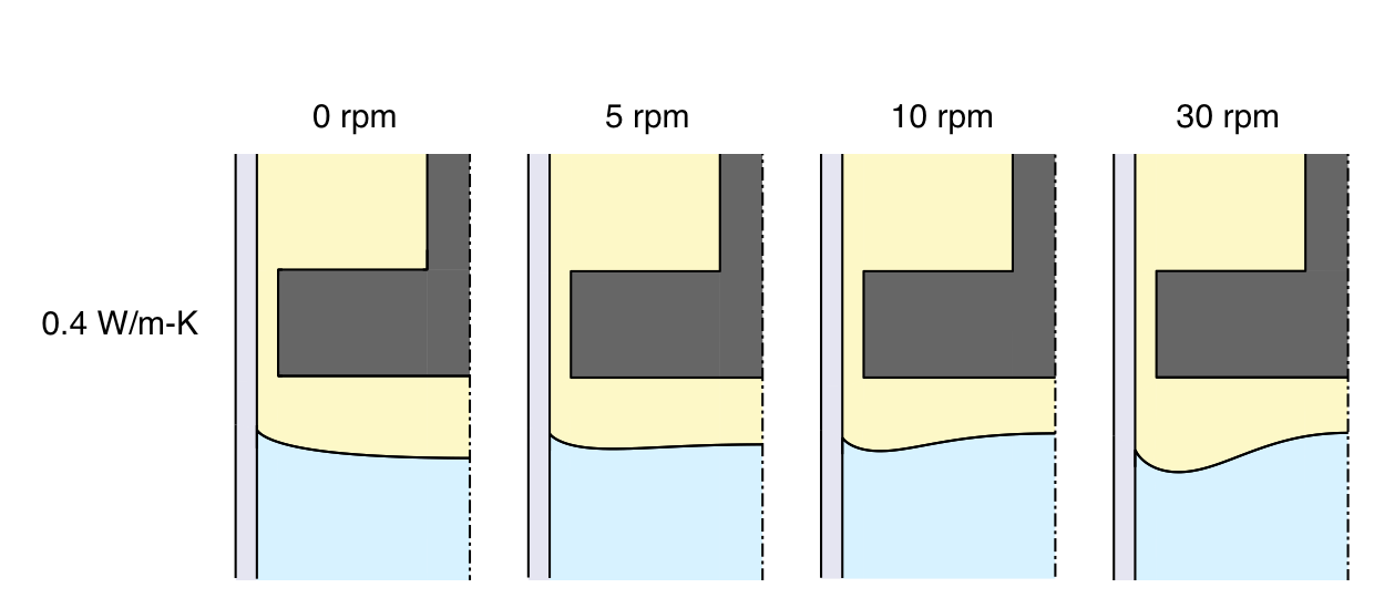
We reconsider the case with baffle conductivity equal to 0.4 W/m-K shown earlier, for which the linear furnace profile gave a concave interface. Rotating the baffle at 5 rpm attains a partially convex interface for this profile, shown below left. Below right is the effect of 5 rpm rotation using the roll-off furnace profile, which is greater interface deflection than shown earlier for this case without baffle rotation.

For the linear furnace profile, rotating the baffle at 5 rpm gives a slightly convex interface that seems pleasing. These next results show that faster rotation rates cause a large concave region to form around the perimeter, which seems undesirable:
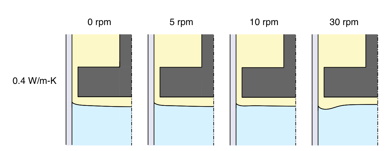
Reducing the furnace temperature profile uniformly by 2 K brings the interface closer to the baffle. The closer confinement of the flow reduces axial velocity and tends to flatten the interface at all rotation rates:
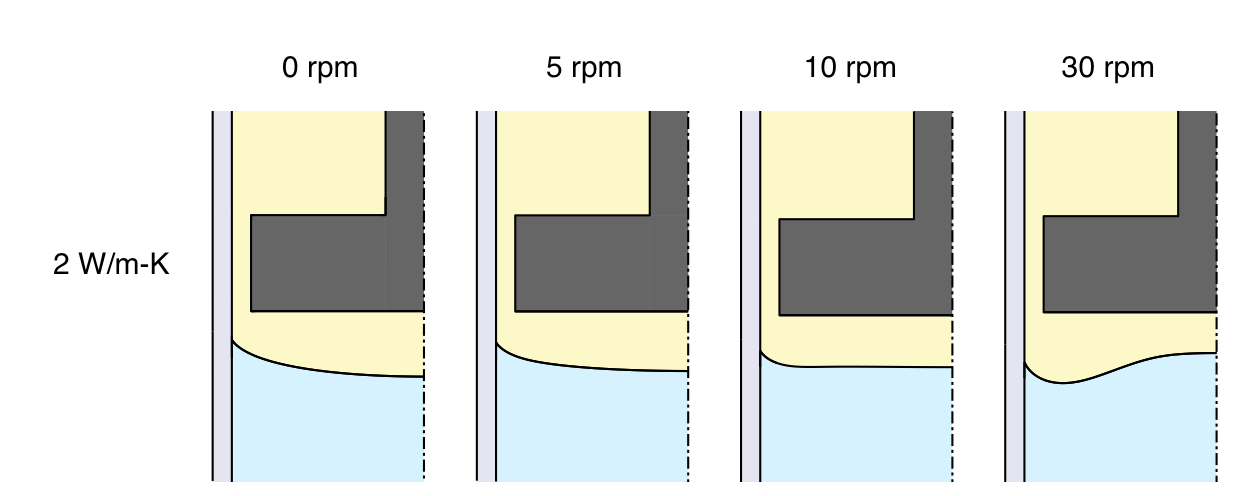
Rotating the baffle to pump heat away from the interface can invert the interface even when the baffle is not insulating, though we must rotate faster to do so, as shown here for the linear furnace profile:
It is possible to invert the interface at a lower rotation rate by using the roll-off furnace profile, as shown here:
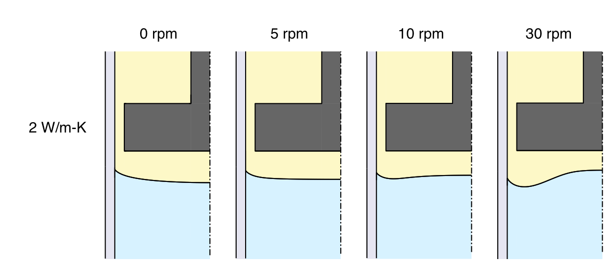
Rotating the baffle makes it possible to invert the interface with it placed further from the interface than were it stationary. This seems beneficial because operating at a larger gap would require less precise control and generally seems less risky.
Pumping heat away from the interface causes the temperature gradient in the melt to drop. The curves shown below indicate that the gradient has fallen by half at 10 rpm. At 30 rpm, the gradient is close to zero near the center axis, a dangerous situation that should be avoided to prevent morphological instability. But it should be noted that mass convection away from the interface is also enhanced, which is a stabilizing influence.
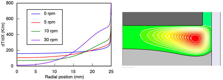
Rotating the baffle is effective at inverting the interface near the center axis, but fails to solve the problem near the ampoule wall where a concave ring persists around the periphery. Melt flows downward near the wall, which traps latent heat and raises the temperature there. In the next section I test some ideas how to deal with this, and come to the sad conclusion that it is essentially impossible to prevent it from happening.
7. What else can we try?
We can reverse the direction of flow near the wall by rotating the ampoule while holding the baffle stationary. In principle this should enhance removal of latent heat near the ampoule wall. I've tried this and found that it doesn't have much impact near the wall. Flow goes to zero at the wall no matter which direction the vortex circulates. Consequently, the angle at which the interface meets the ampoule is determined almost entirely by conduction in the crystal and ampoule, irrespective of convection in the melt. Reversing the flow simply makes the interface more deeply concave in the center.
Latent heat generated near the ampoule wall tends to seek a lateral pathway through the wall. To discourage this I've tried adding a local heat source imbedded in the ampoule just below the interface. My hope was to raise the local temperature enough to melt back the interface near the wall and reverse the radial temperature gradient there. This too failed. The entire interface moved lower in the ampoule while maintaining a concave shape around the periphery.
In these studies I've assumed that the interface coincides with the planar melting temperature of pure CdTe, which is a constant. I've shown that heat transfer in this material always forces this isotherm to bend in the concave direction at the wall, constraining the interface to do the same. From this I've concluded that it is basically impossible to achieve a convex interface shape at the wall in a realistic furnace. If it is true that defects propagate in a direction perpendicular to the growth interface, a partially convex interface might be better than a concave interface. Still, I find it unsatisfying to make so little progress at controlling the interface shape at the ampoule wall, where it seems to matter most.
On the other hand, a suggestion emerges here that perhaps the interface should not coincide with an isotherm if it is to avoid concave bending at the wall. The melting temperature is not truly a constant as treated here, but depends on chemical composition on both the Te-rich and Cd-rich sides of the phase diagram. A melt that is significantly rich in Te, for example, can have a melting temperature that is lower than stoichiometric CdTe, and the interface shape will depend in part on the spatial distribution of excess Te. It might be possible to manipulate heat and mass transfer together to achieve a favorable interface shape, but the interaction is too nonlinear to speculate further without performing model calculations that include mass transport and a proper representation of the CdTe phase diagram. This is something I will probably do soon.